
2014年6月13日星期五
SM6 project meeting for PLN indonesia
2014年5月8日星期四
Mongolia KYN28 switchgear inspection and MV VFD
Our Mongolia EPC customer and ender user , the third party supervisory organization come to our factory to inspect the goods which they ordered .As the system is designed not good ,when we get that order . According to our engineer , we make a good solution and make the system much convenient to operate . The ender user praise our design very much .
During inspeciton , We make the test according to IEC standard and pass for each item . The good quality and good service get our customer approval very well. For next step , they will have MV VFD products for the project , and they will keep to cooperate with us on this products .
QQ:498489025
Email: mark@cncele.com


2014年4月28日星期一
Restricted Earth Fault Protection of Transformer
Restricted Earth Fault Protection of Transformer
An external fault in the star side will result in current flowing in the line current transformer of the affected phase and at the same time a balancing current flows in the neutral current transformer, hence the resultant electric current in the relay is therefore zero. So this REF relay will not be actuated for external earth fault. But during internal fault the neutral current transformer only carries the unbalance fault current and operation of Restricted Earth Fault Relay takes place. This scheme of restricted earth fault protection is very sensitive for internal earth fault of electrical power transformer. The protection scheme is comparatively cheaper than differential protection scheme
Restricted earth fault protection is provided in electrical power transformer for sensing internal earth fault of the transformer. In this scheme the CT secondary of each phase of electrical power transformer are connected together as shown in the figure. Then common terminals are connected to the secondary of a Neutral Current Transformer or NCT. The CT or Current Transformer connected to the neutral of power transformer is called Neutral Current Transformer or Neutral CT or simply NCT. Whenever there is an unbalancing in between three phases of the power transformer, a resultant unbalance current flow through the close path connected to the common terminals of the CT secondaries. An unbalance current will also flow through the neutral of power transformer and hence there will be a secondary current in Neutral CT because of this unbalance neutral current. In Restricted Earth Fault scheme the common terminals of phase CTs are connected to the secondary of Neutral CT in such a manner that secondary unbalance current of phase CTs and the secondary current of Neutral CT will oppose each other. If these both electric currents are equal in amplitude there will not be any resultant current circulate through the said close path. The Restricted Earth Fault Relay is connected in this close path. Hence the relay will not response even there is an unbalancing in phase current of the power transformer.
2014年4月24日星期四
New Automatic transfer switch ,MCB show in 115 Contan fair
We participate in the 115 canton fair during 14 -20 Sep . New type Automatic transfer switch , MCB attract lot of customer and they are interested with our new products very much . This time we show Circuit breaker , Ac contactor , Switchgear , Power transformer in our booth . Lot of old customer some to us and they want to have deep cooperation with our products.
QQ:498489025
Email: mark@cncele.com

2014年4月1日星期二
Russian substation
29th March , Our Russian customer visit our factory in Shanghai . They order our GGD switchgear 2 years ago and our new factory give him deep impression .He want to have more cooperation with our products, and support them to build the substation in russia. The substation mainly contain LV cabinet , MV cabinet and transformer cabinet . He can use our GGD switchgear in the LV cabinet , and as the capicity of room, the MV cabinet will use Solid inslution switchgear .
Skype: mark2002719
QQ:498489025
Email: mark@cncele.com


Skype: mark2002719
QQ:498489025
Email: mark@cncele.com
2014年3月11日星期二
Hydro Power Generation system
Hydro Power Generation(Best solution from China)
Power generation in a country plays a significant rall in any country. The Development of a country highly depends on the power availability of the system.
1.0 Methods of generating electricity
I. Static electricity – Physical seperation and transport of charge, Ex: Lighting
II. Electro magnetic induction – Generator/ alternator or dynamo driven by a turbine converts kinetic power in to electric power. Hydro/ thermal/ wind /neuclear/geo thermal or tidal power can be used to drive the turbine.
III. Electrochemistry – Directly converts chemical energy to electricity. Ex : Battery
IV. Photoelectric – Converts light energy to electric energy
V. Thermo electric – Converts temperature difference in to electricity
VI. The mechanical strain of electrically anisotropic molecules or crystals.
VII Nuclear transformation – The creation and acceletation of charged particles(Ex: betavoltaics or alpha particle emission)
- However when it comes to electricity generation in industrial scale, only Electromagnetic induction and Photoelectric actions used to generate electricity.
- For the electromagnetic induction method, Hydro power / Thermal power / Wind power / Nuclear power / Bio mass power / Tidal power/ Geo thermal power/Dendro power/ plasma gasification and vitrification process are used as sources to drive the turbine. But in Sri Lanka only Hydro – Thermal – Wind – Bio mass-Dendro-Solar-Plasma gasification and vitrification process – resources are used to generate country electricity need.
1.1 Hydro power generation
Hydro power generation is very economical environmental friendly way to generate electricity. But it needs comparatively large capital to innitiate. It is catagarized in to 3 stages,
- Large hydro power stations – Connects directly to the national grid (Typically to 132kV or 220kV)
- Mini Hydro power stations – Connects to the medium voltage line (Typically 33kv/66kv) lower than 10MW of generation.
- Micro Hydro power stations. – For industries or housing schemes isolated by the network. It is not connected to the national grid.
- Generally in a hydro power station it consist with – Dam , Penstook , Surge chamber, MIV, Wicket gates, Turbine, Draft tube, Generator, Governor, Bearings, Main shaft, excitation generator, Control pannel, Protection schemes, switch yard, transformers,Tail raise.
- Generators runs fully time. So then the temperature at bearings increases considerably. therefore, cooling methods are required. Air cooling and oil cooling is used here. The total weight of the turbine and axel is about 130tons. and this weight is hold by thrust bearing. To reduce the wear and temperature of the bearing , high compressed oil is used.
- For UGB and LGB oil was used as the cooler.
- For windings air circulating system was used.
- Francis Turbines are the best suite for a location like kothmale.
- Every turbine is characterized by a constant, specific speed(Ns).defined as,
N – Shaft Speed H – Rated head P – Rated Out put Ns = N P 1/2
H 5/4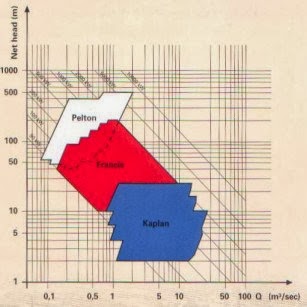
Turbine typesPelton wheel Francis type I Francis type II |
- The turbine type is determined by considering above mentioned Ns
- There are two main gates to control the water flow in the power house. ie. Main inlet valve and wicket gates. When the generator starts,the MIV is opened by aid of a bypass valve and opens the runnerway till the wicket gates. and wicket gates are opened upon the control of governor and regulate the water flow. wicket gates are connected through a ring and this ring moved by two servo motors which are controlled by the governor. machine speed is fully controlled by opening and closing of wicket gates.
- Governor is like the heart of a hydro plant. It guides the machine in to a specified sequence and maintain the machine basicaly in two modes. ep1 and ep2. ep1 mode is basically more sensitive to the system frequency and controls wicket gates to maintain the system frequency at the rated value(50Hz in SL). ep2 mode is more sensitive to maintain the machines output power at a pre-determined value. It keeps the machine at a nominal power output value and supports frequency control by a little.
- The basic concept of this two methods is “droop control”
- Kothmale power station sometimes having the chance to control the system frequency in Sri lankan network. In that moment, from three machines- one machine is running at half load of it’s full capacity and another machine is running at ep1 mode which is more sensitive to the system frequency.
- You can’t have two system frequency controlling machines at once. Because they will mutually try to increase or decrease system frequency. the result is, system fluctuations and lot of unnecessary work by governors together.
- What happens if your governor fails ???
- Hahh haa… Once I have been asked the same by an interview panel
- If the governor fails, the machine will run without control. the result is – No control of the water flow and generation demand –> Machine accelerates –> Frequency will increase –> Machine will trip due to Over frequency –> MIV will closed the gate.
- (Tell this if you happened to asked by an interviewer
- System Black outs ….
- The most risky time is when your system runs at it’s minimum loading(off peak – early morning hours )
- If any generator trips due to system fault or machine fault or what ever, the system experience a sudden frequency drop due to load – generation gap. The amount of frequency drop is basically determined by the amount of generation that system lose.
- Generators having specific parameter called, “Machine natural frequency”. In this frequency , if you run the machine – there would be immense vibrations/ oscillations in the machine which is very harmful to itself.
- Most of the time this natural frequency of machine lays very near to 50Hz which is again the operating frequency of same machine.
- If system frequency drops down and when the generator follows that frequency, near this particular value , generator trips itself to avoid possible mechanical hazards to the machine due to natural frequency.
- Can you imagine the result: The system will lose another generator unit and further decreasing of system frequency.
- This would happened cascade and controlling center would lose it’s control. And also the frequency controlling machine would not have enough capability to handle such situation. The result would be a black out !!!
- To avoid this, there is some thing called Load Shedding Schemes.
- Load shedding scheme is monitoring system frequency and if any under frequency happens, it trips system load/demand centers and try to help in matching demand and generation. { if I explain again the scene here: We were talking about a scenario where there generation is much less that the demand and continuously increasing this gap}.
- Load shedding scheme monitors the ” Rate of change of frequency ” and shed loads before the frequency comes down to a dangerous limit and helps system control generator to keep it’s controlling.
- After system becomes normal, this shredded loads will connect to the system again.
1.5 Excitation methods
 All synchronous machines except certain machines like permanent magnet generator require a DC supply to excite their field winding. As synchronous machine is a constant speed generator for a constant frequency power generation , the output voltage of the machine depends on the excitation current.
- There are two excitation systems available,
1. Static Excitation
2. Dynamic Exciter
And different types can be catogerized as,
1. a. Seperately Excited DC Excitation
1.b. Self Excited (shunt) DC Excitation
2. High frequncy AC excitation
3. Brushless Excitation
4. Static Excitation

- thyristor type static excitation.
- The main advantage from brushless excitation over a static type excitation is, no carbon particles emitted by brushless type. the carbon particles emitted by brushed type excitation units are depositing in wires and circuitry. This is leading to a generator faults and wrong indications in the protection scheme which is a very bad effect to the plant efficiency and reliability. Because machines might undergo immediate shut downs due to wrong faulty indications.
| Table 1.1: Excitation systems |
| Brushless Excitation System | Static Excitation System | |
| Maintenance | Low | High |
| Response | Slow | Fast |
| Losses | Less | High |
| Maintenance cost | Less | High |
| Excitation current | Less | High |
| Emition of carbon particle | No | High |
| Excitation transformer | Small | Large |

1.7 Equipment used in switch yard
1.7.1 Wave Trap
Wave traps being used to trap the “Power Line Carrier “ massage signals and filter and send to communication system. PLC communication is used in between power stations and system control center and all the grid substations. It is a reliable method to communicate. Wave traps are seemed to be high impedance to low frequency power waves and negligible impedance to high frequency massage signals. Wave trap also used to find line faults indications.
1.7.2 Potential Transformer (PT)
PT’s are used highly in high voltage, voltage measurements. Basically it is a transformer and the secondary side induced voltage is taken in to measurements.
1.7.3 Current Transformers (CT)
Current transformer is just like PT but it uses it’s secondary current to measure current in the line.
1.7.4 Capacitor voltage transformer (CVT)
CVT is a transformer used in power systems to step-down high voltage signals and provide low voltage signals either for measurement or to operate a protective relay. In its most basic form the device consists of three parts: two capacitors across which the voltage signal is split, an inductive element used to tune the device to the supply frequency and a transformer used to isolate and further step-down the voltage for the instrumentation or protective relay.
The device has at least four terminals, a high-voltage terminal for connection to the high voltage signal, a ground terminal and at least one set of secondary terminals for connection to the instrumentation or protective relay. CVTs are typically single-phase devices used for measuring voltages in excess of one hundred kilovolts where the use of voltage transformers would be uneconomical.
1.7.5 Circuite Breakers
Circuite breakers are playing a very important role in power line protection. There are many kinds of circuite breakers. The difference between them is the medium used in the breaking point. A highly resistive medium is used at the point where break happens. The reason is, when switching occurs at a voltage of 132kV or 220kV a huge arc can be occured and damage the instruments making system unstable. To prevent from this hazzards, suitble technology is used. From the highly resistive medium, it prevents the arching effects. and the breaking is done withing a short period of time. Normally the time ranges in few milli seconds. This is also to reduce arching effects.
- OCB- Oil cct Breakers- Oil is used as the medium.
- SF6 – SF6 gas is used as the medium.
- Vacum – A vacum is used as the medium
1.7.6 Load Breaker.
Load breaker is a device wich is act as a normal switch. It’s operating by metal rods. The main reason to use load breakers is to take an visual assuarance of isolating the line. Load breakers should used after OCB,SF6 or Vacum circuite breaker since it does not having a capability of break the line at online stage.
1.7.7 Surge Arrester.
Surge arresters are used to protect the system from surges. Specially a line like kothmale – biyagama needs this type of protection due to the high possibility of affecting surges. A surge arrester can bear only a certain no of surges . and there is a surge counter there to measure it’s life time. once it reach to the saturation level, we have to replace another one.
1.7.8 Bus Bar.
Bus bar is a conductor where all the lines connected to it in a proper arragement. It can be a pipe type conductor or wire where it’s conductivity is very high.
1.7.9 Power Transformers.
- Power transformers are the devices where transform voltage levels. In kothmale, it is used 13.8/220kV (90MVA) three winding transformers and the G3 was connected to 13.8/132/220kV (90MVA) interconnection three-winding transformer. Three winding transformers made of one transformer for each phase.
- 220kV bus bar was connected Anuradhapura-2, Biyagama-1, Biyagama-2, Victoriya-1 and Victoria-2 while 132kV bus bar was connected to Kiribathkumbura-1, Kiribathkumbura-2, Polpitiya-1 and Polpitiya-2. But at this time, 132Kv line is not working.
1.8 Control Room
The generator opperation can be controlled either in generator room or control room. In kothmale, it’s seperated control room and generator by a considerable distance. But most often, operators start the machine from generator room and the sycronization is done by the control room. Previously, all the cct breakers ware operatable from the control room. But now the system is not functioning well.
1.9 Syncronizing
After starting a generator, we should match it’s Voltage, Frequency and phase with the national system values. If we try to connect Generator without matching these parameters, it could lead for huge electrical torques wich are affecting Gene. machanical system. Therefore we have to care about this matter very sensitively.
1.10 Protection schemes
| Alarm |
| Indication |
| Tripping |
Protection scheme play’s a significant rall in generator unit. Because, as a fulltime running machine, it could be generate a faulty situation at any time and the main thing is, after a fault in the system, the harm to the machine should handled in the minimum level since it’s very disadvantages to shut a generator. From protection system, most of the time we can stop the machine or make the fault fixed before any kind of damage to the machine. We are getting warnings as alarm or indication at the early stages of the fault and if we didn’t take any actions to fix the fault,and the fault lead in to a critical fault, then the machine shut’s it down automaticaly inorder to protect the unit.
1.11 Neutral point earthing method
- Generally the generator Y winding’s neutral point is grounded at the same place in the power house. But here the situation is different and the plant is situated in a hard rock which it’s resistivity is high. Therefore we can’t use ordinary grounding method.
- Specialty of Kothmale power house was grounding of generators were taken place through an earthing transformer at the switch yard and the Pilot wire differential protection for check if there is a leakage of the power cable from generator to switch yard.

2014年3月9日星期日
Africa Angola Substation and switchgear
Africa have a lot of project about building and power . Mr.Wen and his team visit our company for business discussion about substation and switchgear today . They visit our show room , factory and give us high appraise to our company and will use our Substation and switchgear for their project in Africa .

Mainly they now need substation with SF6 RMU(Ring main unit) , transformer and LV distribution . As the special condition of voltage is Angola country 15KV system , we advice to use our 20KV SF6 in the substation . Our customer agree with our advice and they believe it will be good cooperation in the future .
Skype : Mark2002719
Skype : Mark2002719
订阅:
博文 (Atom)